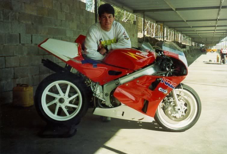
The bike itself is an early prototype VFR-750R built in 1986 and imported into Australia specifically for use as a race bike. I bought it in 1994 and was lucky enough to get it with an engine that was built in 1993 with the full HRC race kit installed.
The bike was retired when the RC45 was introduced and thats when I was able to pick it up for what I considered to be a steal.
I rode the hell out of it, doing 50 or so track days in 5 years before the crank gave up the ghost. Around the same time I decided to move here to the US so I had no time to repair it and just packed it up into a bunch of boxes and put it into storage.
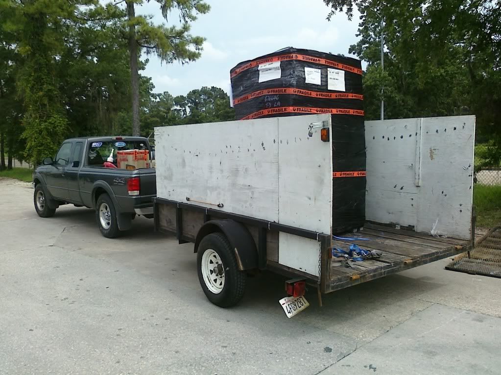
10 years later I was able to bring it over here so I packed it up and it arrived with the thick layer of grease still in place.
It took another 3 years to find all the parts I needed before I could even think about rebuilding it, and then the damn 996 went all Ducati on me and I had to rebuild it just so I could get rid of it. But once that was done I cleared out my work space and got started.
There were a few nasty surprises but nothing I couldn't handle. There were plenty of parts that needed to be repaired/replaced. Most of these were no longer available so had to be made from scratch or replaced with expensive aftermarket parts.
There were a bunch of parts on this bike custom made by the race team that were either broken or worn out but thats why I taught myself how to use Autocad and a bunch of CAD/CAM programs. I built myself a small CNC mill specifically to make parts for this RC30.
So here are some pictures:
My first track day on this bike early in 1994
Picking up the package from the freight hub in Houston
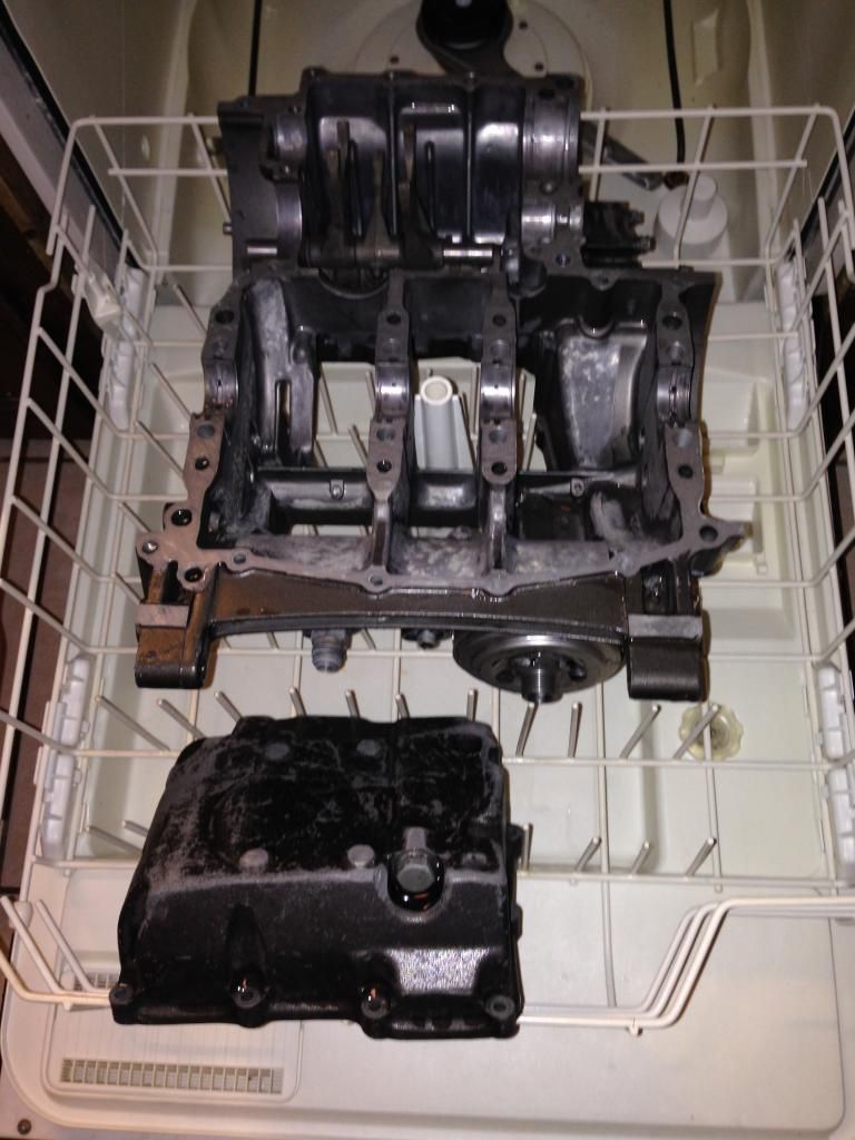
The special parts cleaner in use. It works perfectly.
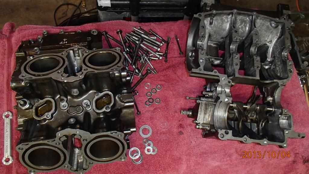
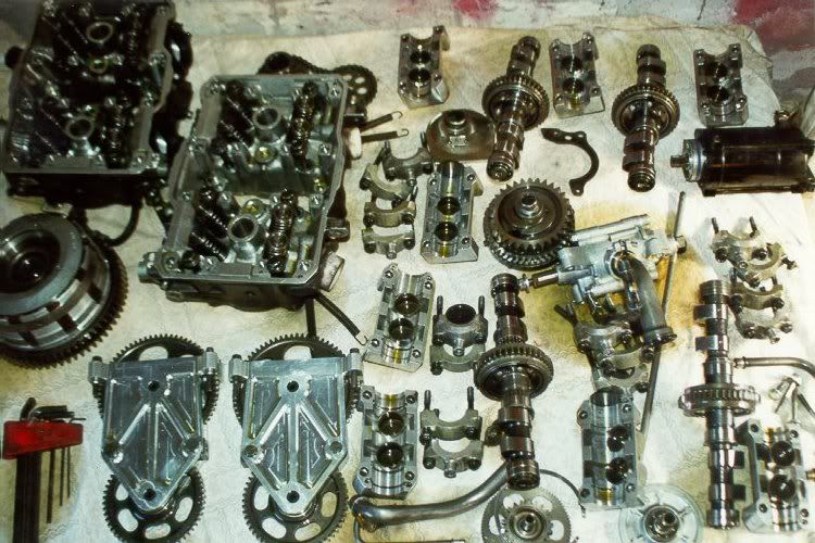
Cases all clean and ready to go back together.
Heres the top end ready to assemble.
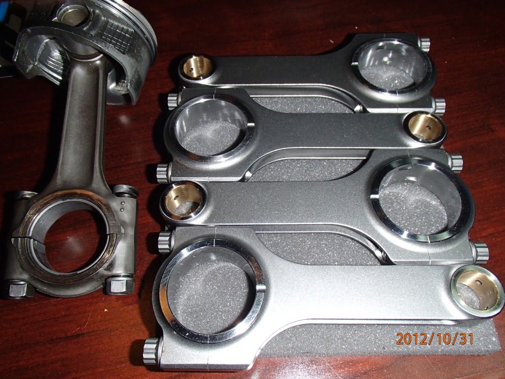
New aftermarket rods cost more than my KTM supermoto. You can see the damage on the original titanium rod but these are not repairable.
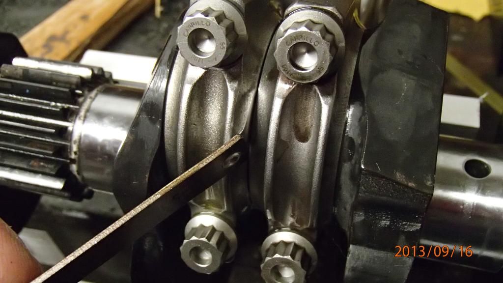
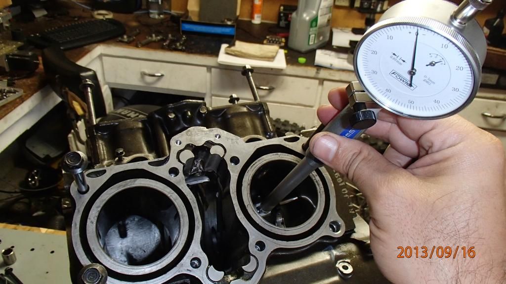
Checking side clearance on the new rods when installed.
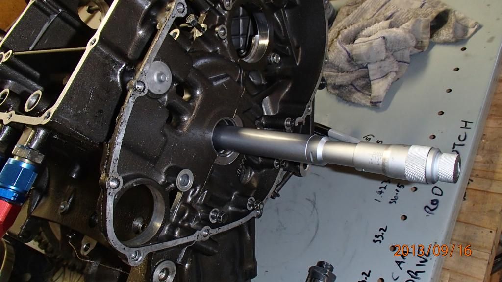
Using the damned expensive internal micrometer to check the custom bearings. Much more accurate than plastigauge provided you take all measurements with the parts at the same temperature.
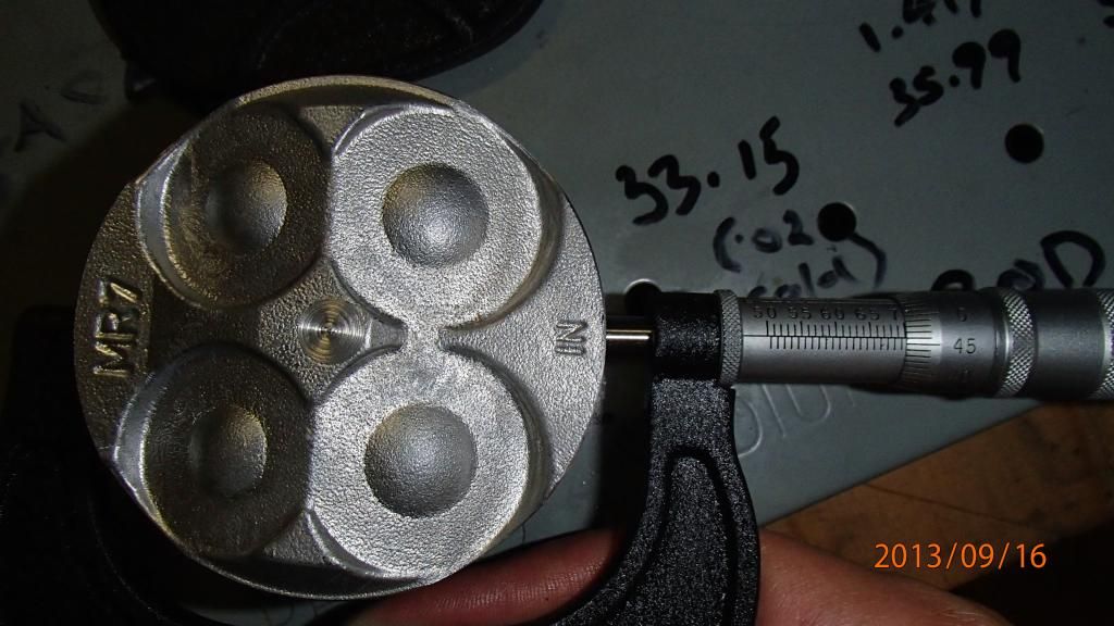
Old pistons are worn out. Thats why the motor was smoking a little the last few times I rode it.
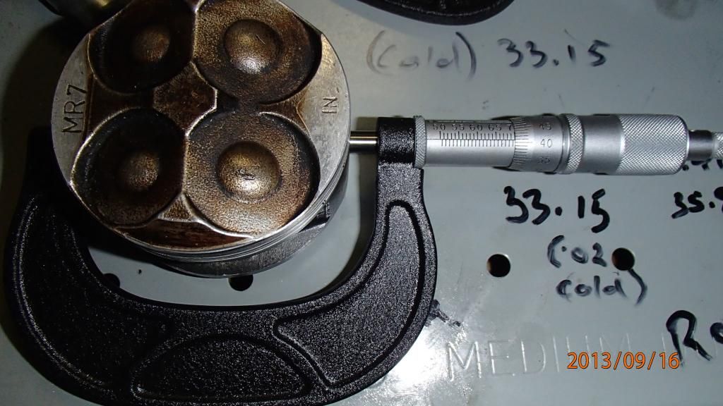
New pistons. Notice the different reading on the micrometer. Thats the difference between smoke and no smoke under hard acceleration.
Checking the cylinders. Thankfully they were still within spec.
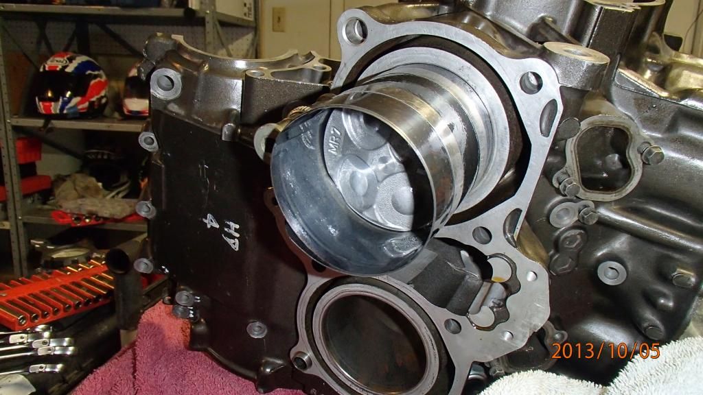
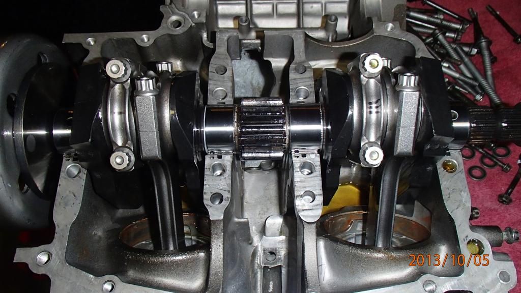
This motor has the cylinders cast into the top crank case. As a result the engine has to come apart any time new pistons are needed. Here they are going in:
From below. Individually weighed and balanced rods and pistons installed.
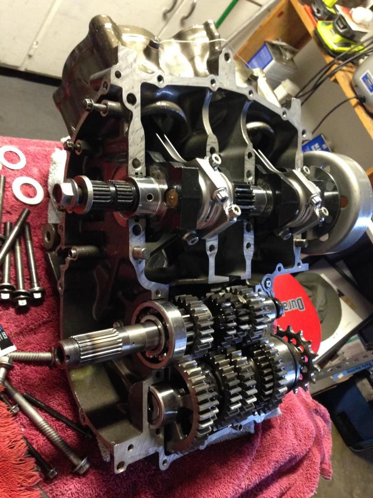
Transmission installed after each gear was washed and all bearings checked.
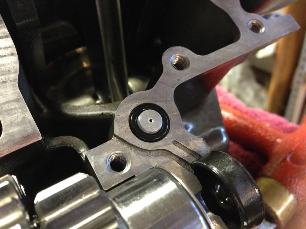
There are four of these oil jets in the cases. Dont forget any or there will be problems.
Cases together. It takes a lot of jiggling.

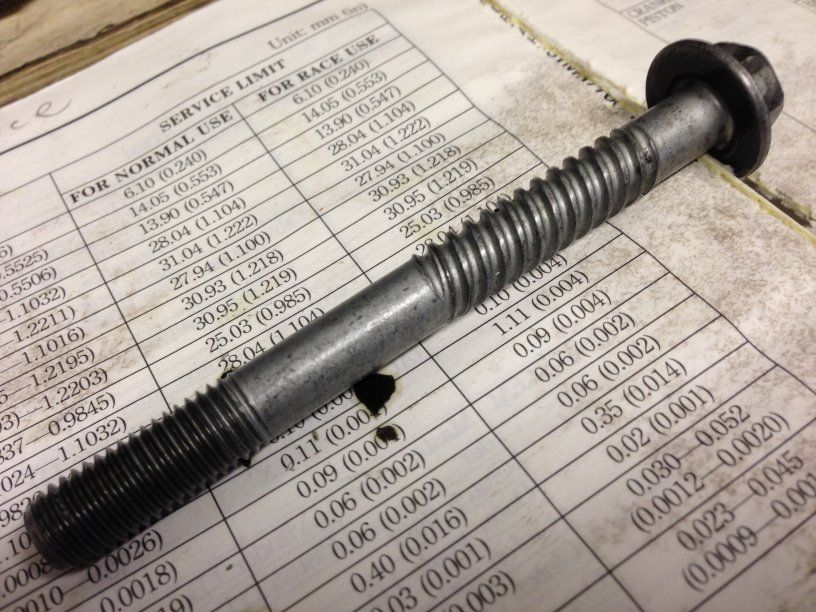
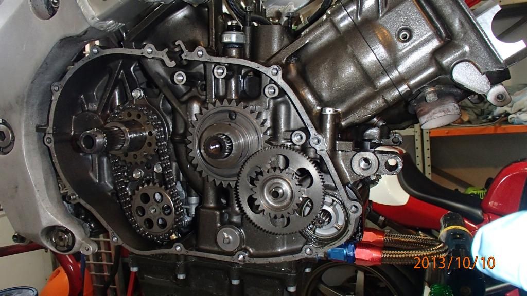
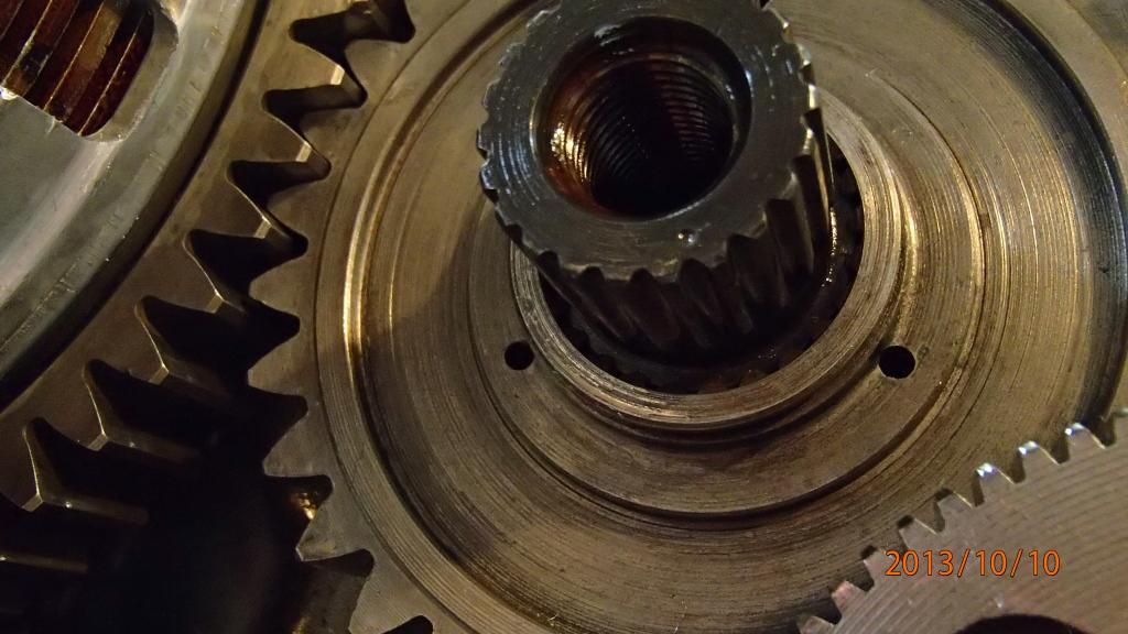
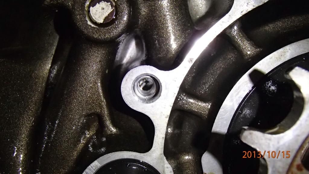
Heres a question - who can shed some light on the spiral groves on this bolt? It holds the cases together so has no interaction with oil or gears. Heads of two of these are visible in the next picture.
Flipped over, this is the oil pump. Its actually from a VF1000R as the standard pump doesnt have passages for the lines to the oil cooler.
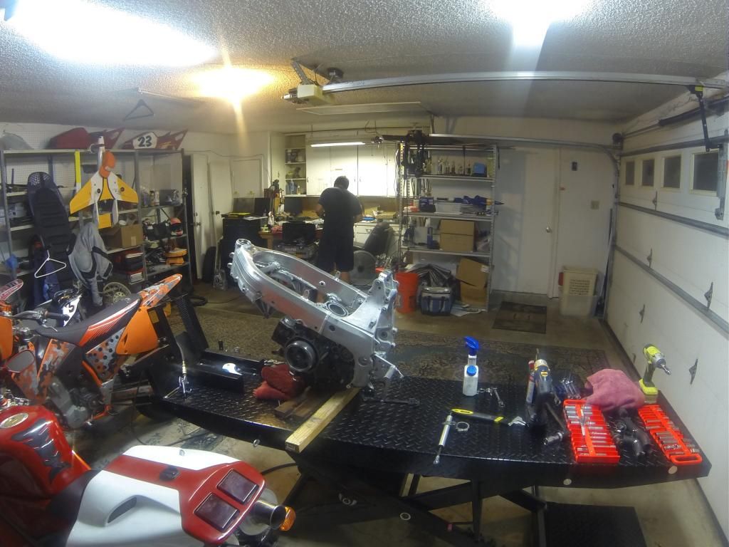
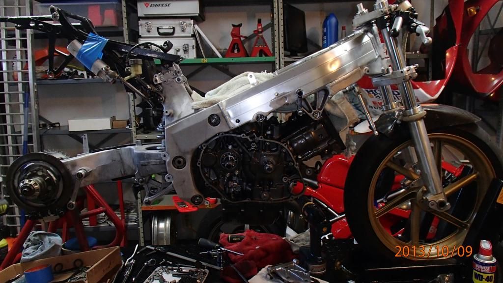
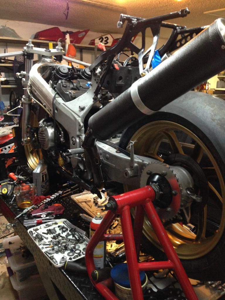
I figured this would be the best time to bring the engine and chassis together. Thats when I noticed the crud in the threads.
Heres a shot from the timelapse - frame installed on the engine.
Roger from OnroadOffroad.com rebuilt the shock and forks.
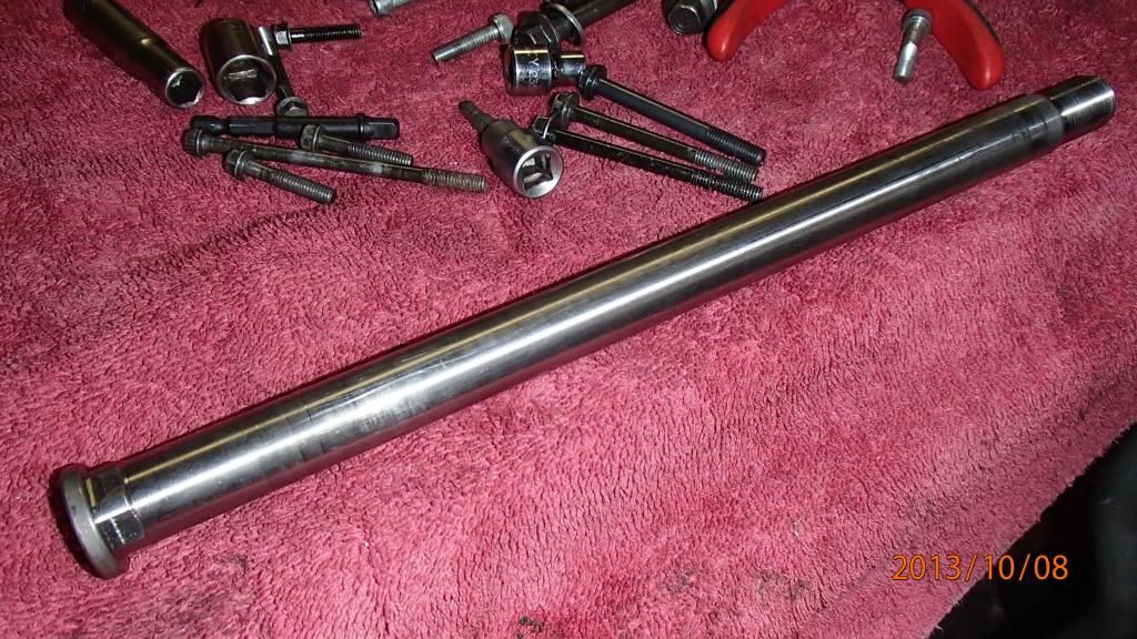
This is the titanium swingarm pivot - part of the HRC kit. It feels light as aluminum.
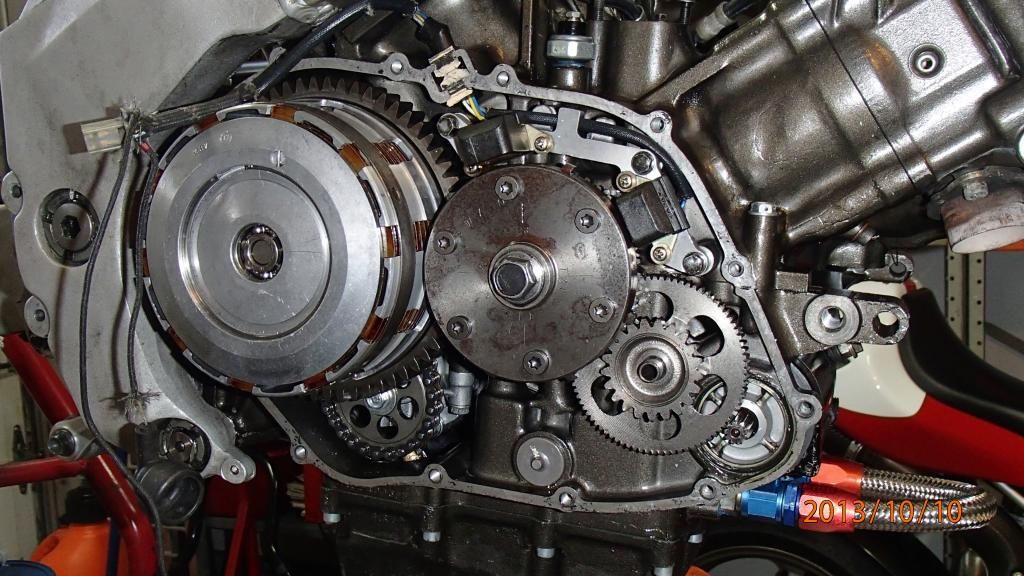
Here are the starter motor and gears I installed when I first got the bike. Why? Bump starting is a real pain.
Race kit crank allows ignition timing to be adjusted.
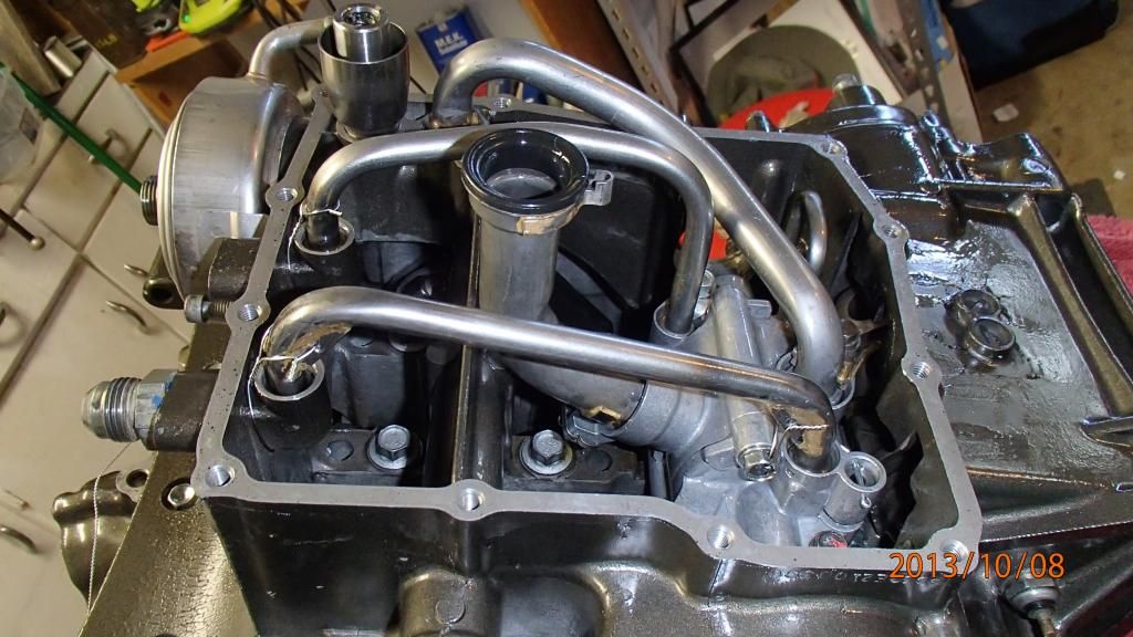
All ready to button up. (oil cooler bypass line waiting for new hoses)
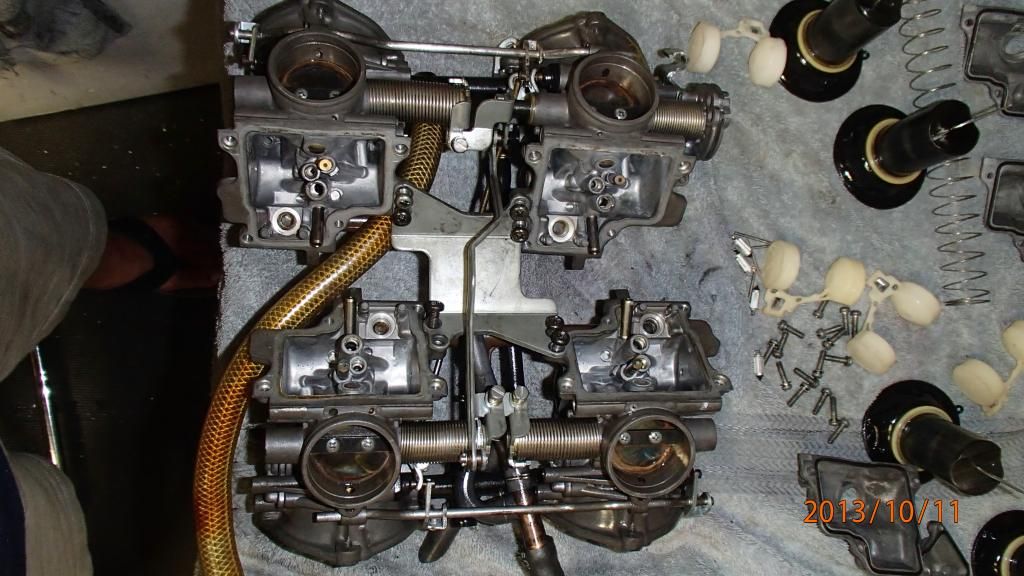
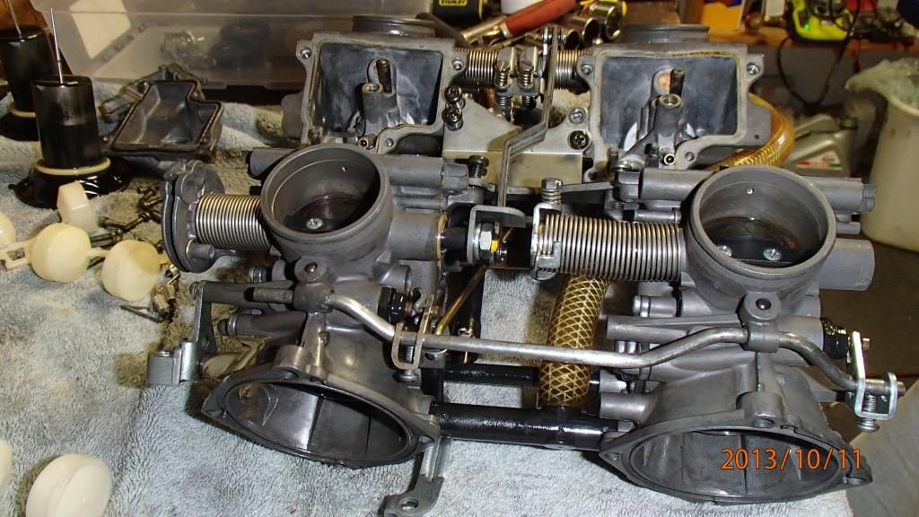
Time to start work on the carbs. Luckily I emptied them before I stored them so they werent bad at all.
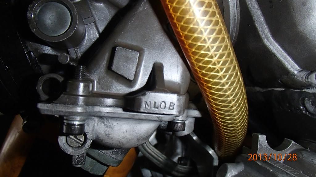
I installed a choke system - not easy with the short-port NL0 heads. But worth its weight in gold.
On the other side of the motor I found some more stripped threads. The race team helicoiled almost every bolt hole in the motor for reduced weight. I did the rest.
Coming together nicely.
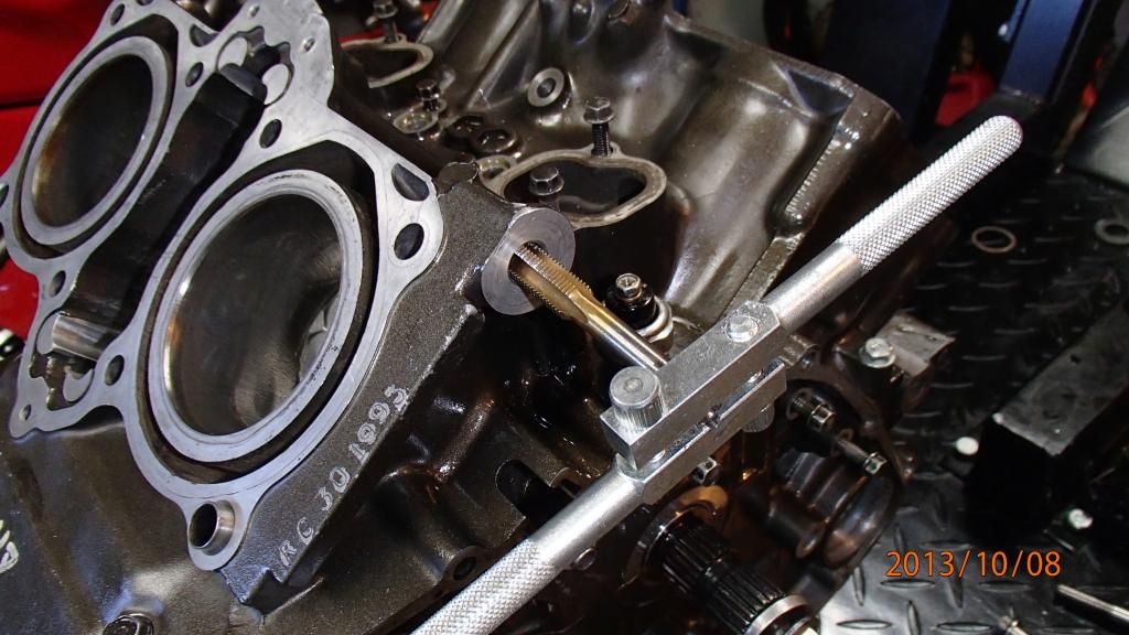
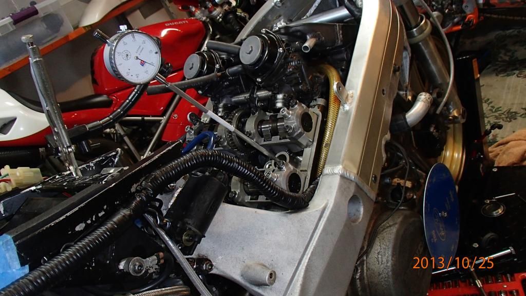
Checking piston travel to verify cam settings.
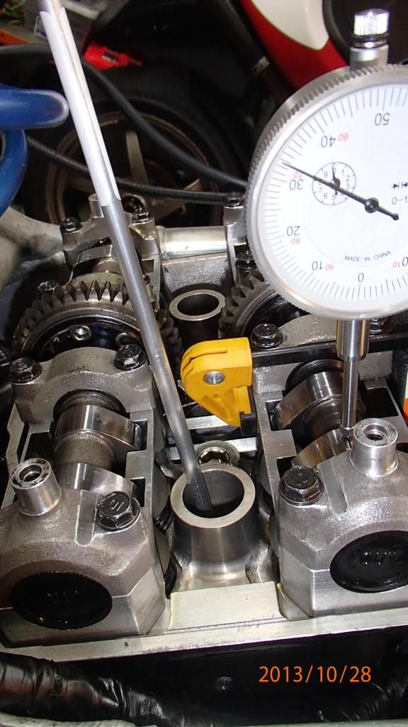
Checking cam travel. There is actually a degree of difference between the front and rear intake cams. Not sure which one is wrong though. I cant adjust until I know which one is correct.
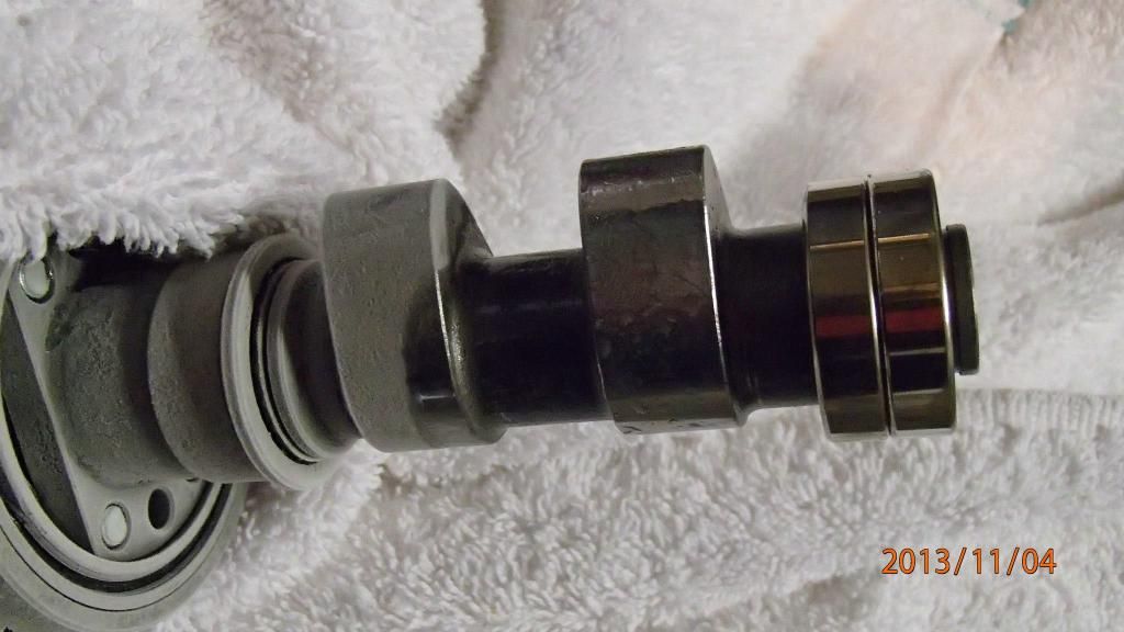
I then found a bad bearing on the front bank so I replaced both. Here the hot bearing drops onto the chilly cam.
Race kit ID mark.
Now comes the fun part. The stock wiring harness is huge and heavy. So I ordered a VFR-F harness to donate wire and connectors for a new harness made to the race kit wiring diagram.
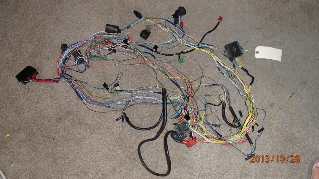
I later found out that there were several plugs missing from the F model harness. I found a goldwing harness that had all the plugs I needed and it was an easy process to make the new harness with starter motor and charging circuit added.
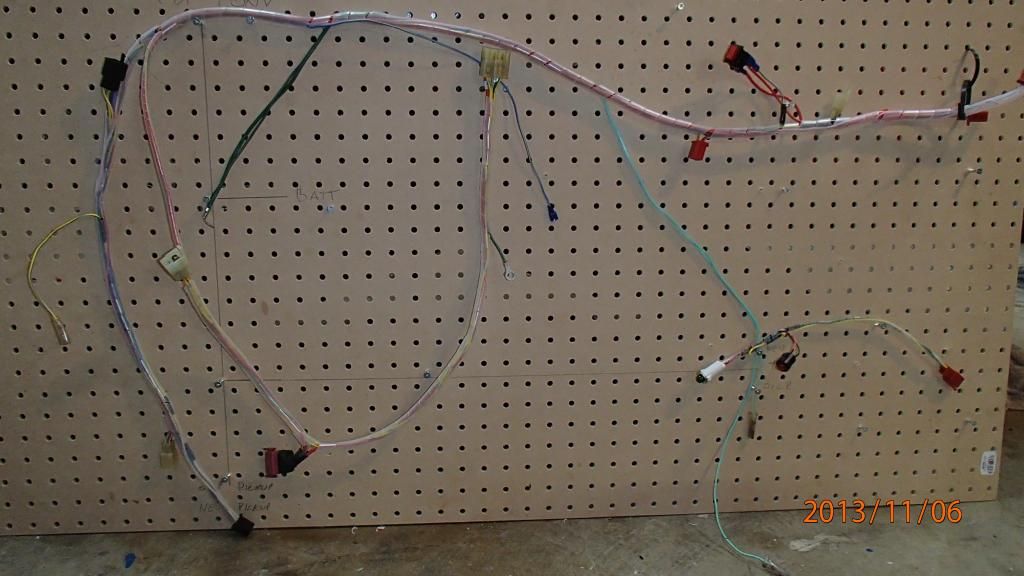
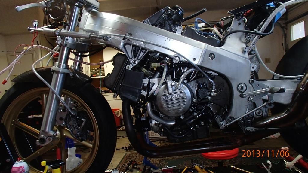
Kit CDI connected to the new harness. We now have sparks in all the right places.
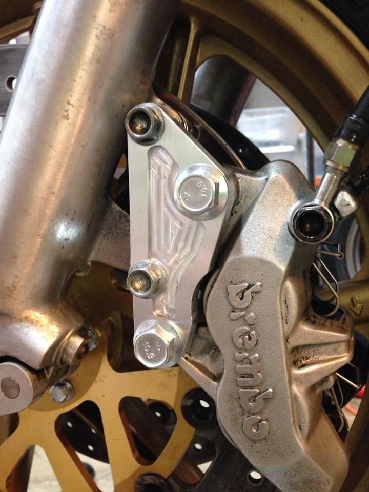
Heres the new brake calipers mounted with custom made brackets. The old calipers needed new seals that were no longer available. Hopefully these calipers from a 999S will work as well as the AP Lockheed ones. (Thats not dirt on the calipers, the previous owner painted them then scraped most of the paint off. Theres a little more left to do though).
And here it is running:
http://youtu.be/fyLLQviL3To