VFR750R-RC45 Ignition Tuning

All models of RC45 from RR to RS had some sort of restriction. Some easy to remove, some less so!

Japanese models

These models are restricted in a number of ways down to 77PS. First is the PGM-FI unit. This needs to be replaced with a UK part marked 'ED'. Second is the inlet manifolds. These have metal plates cast into the plastic throat of the manifold. They can either be replaced with the standard UK part or using a little skill ground out. Third is the exhaust. In this case the silencer. Again this will need to be replaced with a standard UK item. Once these modifications are done power should be increased to around 98PS.

French models

Again the PGM-FI unit needs to be replaced with a UK 'ED' marked one. These models are also fitted with lower lift camshafts so will require these to be exchanged for any of the other model type cams. This is quite easy to do as the cams are a straight bolt-in modification, requiring only the checking of the valve clearances after installation.

USA models

These bikes came with full-power PGM-FI units but were restricted via a harness modification. This can be reversed by following the Honda instructions. This modification can in fact be made to ALL RC45’s, including UK ones, and will also remove the top gear soft limiter and increase the rev limiter to 13,000 from the stock 12,500.

RC45 Wire Splice

RC45 Wiresplice Instructions

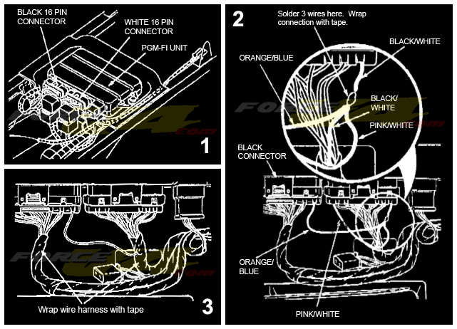
  1. Disconnect the battery. Locate the PGM-FI unit at the rear of the subframe under the seat cowl. Disconnect the white 16-pin and black 16-pin connectors from the ECU. Strip approx 80mm of the PVC insulation from the harness with the white plug, and approx 60mm insulation from the side with black plug.

  2. Locate the black/white (+12V) wire on the white 16-pin connector. Strip 8mm of insulation from the Bk/Wt wire (do not sever the wire) approx 50mm from the connector.

    Locate the pink/white wire and cut it approx 100mm from the connector and strip 6mm of sleeve from the end. Insulate the end of the pink/white wire on the harness side with electricians PVC tape or heat-shrink.

    Locate the orange/blue wire on the black 16-pin connector. Cut the orange/blue wire approx 120mm from the plug and strip 6mm of sleeve from the end. Insulate the orange/blue wire on the harness side with electricians PVC tape or heat-shrink.

    Solder the pink/white and orange/blue wires to the black/white wire. Insulate the join with PVC tape or heat-shrink.

  3. Wrap each the end of the harness with electricians PVC tape to neatly finish the job.